MICHAEL TIMBER FRAMER INSTALL
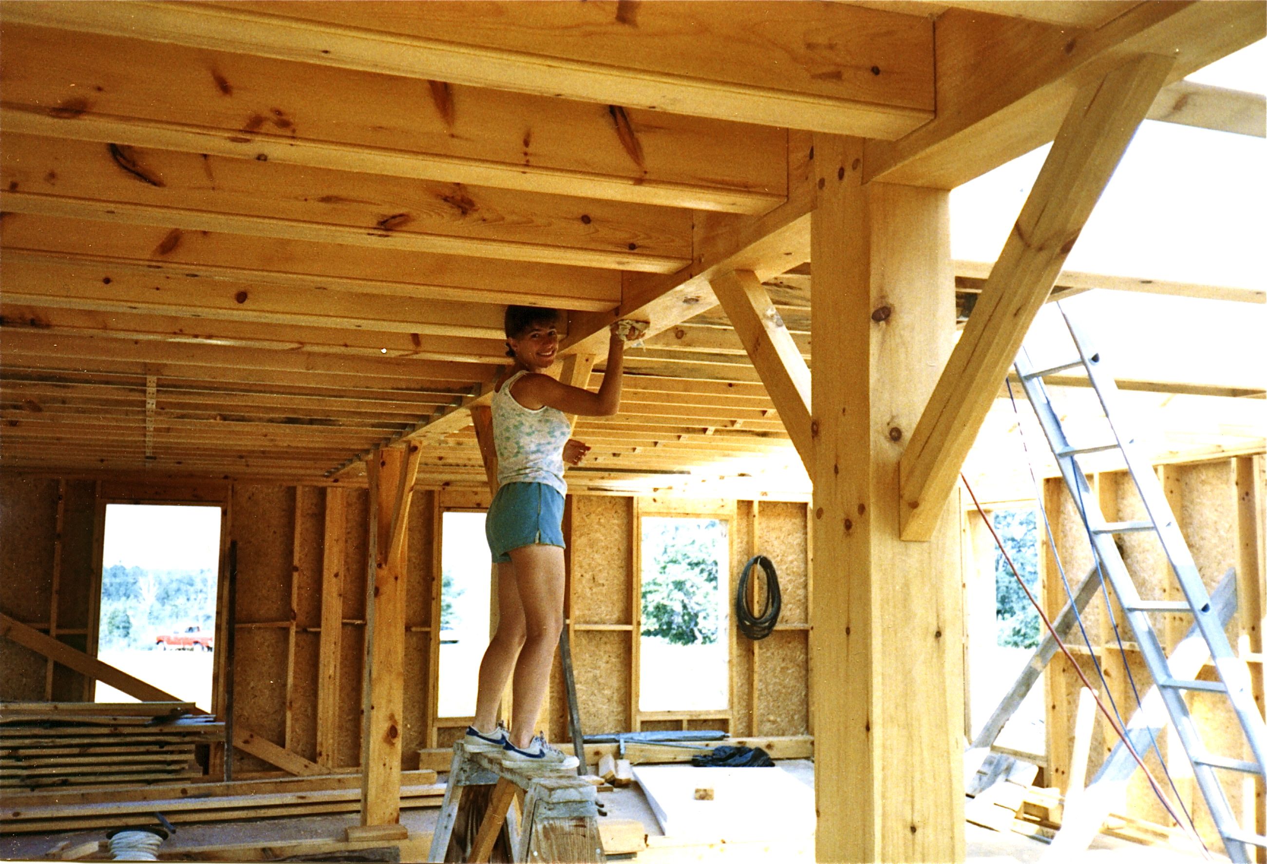
Since I felt no need to create an attic and wanted the cathedral ceiling look, the beams and girts did not have to meet at the same point on the posts to create the ability to install a flat floor. The roof framing, like the deck, also follows traditional joinery techniques. The bay girt splines run the opposite direction, divide the top of the posts and are set in long mortises along the top of the girts. The bent beam splines run through the posts to support the beams from underneath. At these four points, two splines were needed. The joining of the bent beams and bay girts at the central box corners involved the intersection of four beams all at one point. If the post is eight inches wide, the bent beam housings are both three quarter inches deep, and the peg ends are one quarter inch inside the back of the bent beam housings, then the bay girt peg has to be six inches long. I made sure that the peg end remained one quarter inch behind the back of the beam housing and was driven one quarter inch deeper than the back of the other beam housing. This bay girt peg can not be driven so far that it contacts the inside of the opposite housing. Otherwise, the two bent beam-ends cover the peg site for the bay girt since the peg for the bay girt tenon is inside of the bent beam housing. The trick here is to install the bay girt before both of the bent beams are attached to the spline. In the case where three beams meet at a post, I resorted to using a single spline for the bent beams and pegged the bay girt. As I inspect these joints that are now between five and seven years old, the average gap between the post and beam is about one quarter of an inch so one half inch of housing is still engaged. Thus, the three quarter inch housing, after the post and beam shrank would still be at least half engaged. Therefore the eventual shrinkage at a post to beam joint would be about five sixteenths of an inch. I also assumed that the width of a post would shrink at most about a quarter of an inch on each side. I assumed that the length of a beam would shrink at most about an eighth of an inch, or about one sixteenth at each end. This housing, mortise and tenon design is based upon my assumptions of potential wood shrinkage over time.

This puts the one inch peg edge one quarter inch inside of the housing and two and three quarter inches (the relish) from the end of the tenon. When I created mortises, I made sure that they were at least one-quarter inch deeper than the four-inch tenon. Thus, the tenon is three and one quarter inches long and the peg center is placed one and a half inches from the outside of the beam. All of the tenons are one and a half inches by four inches including the three quarter inch deep housing. The post is free-standing (it has a copper plate underneath it to protect the wood from the concrete floor) and when the right hand beam tenon slides into its mortise, the connecting beams will rest on top of the post while the two scarf joints also fit together.Īll of the beams have housings that are one inch less than the beam size on the bottom and each side.

Above is the joining of the west center set of basement spanning beams. The previous photos are of the assembly of the east center set of basement spanning beams. I chiseled my initials and "1-1-96" when I made this mortise - Happy New Years day! The lower date, "6-18-96", is the date that this joint was put together. The photo above is a close-up of the mortise for the beam tenon that the crane is holding. The engine crane is placing one half of the connecting beam that will span to the opposite side of the foundation and connect to a similar set of sill beams. In the photo below, these two timbers are joined end to end on top of the concrete foundation wall. On the left, the mortise has been fine tuned for the correct depth and straight back and sides of the mortise. With the mallet and chisel in the center, the excess wood has been removed.

Three holes were drilled to remove much of the wood. On the far right next to the drill, the mortise sides and back have been cut with a circular saw. The photo to the left shows the process of cutting three of the six dovetail mortises that are in one of these sill timbers along with the tools employed.


 0 kommentar(er)
